ESP32S3N8R8 + lvgl测试官方案例
说明
硬件:立创ESP32S3R8N8开发板 + 2.8寸TFT显示屏(ST7789) + 电容触摸(GT911)
软件:Visual Studio Code + PlatformIO
代码:百度网盘:ESP32S3_GT911TOUCH(提取码:levi)
视频:bilibili: 【ESP32】2.8寸电容触摸屏(ST7789+GT911) lvgl 案例测试
博客:CSDN: 【ESP32】立创ESP32S3R8N8开发板+2.8寸TFT电容触摸屏ST7789+GT911+PlatformIO
新建工程
点击侧边
PlatformIO插件,新建工程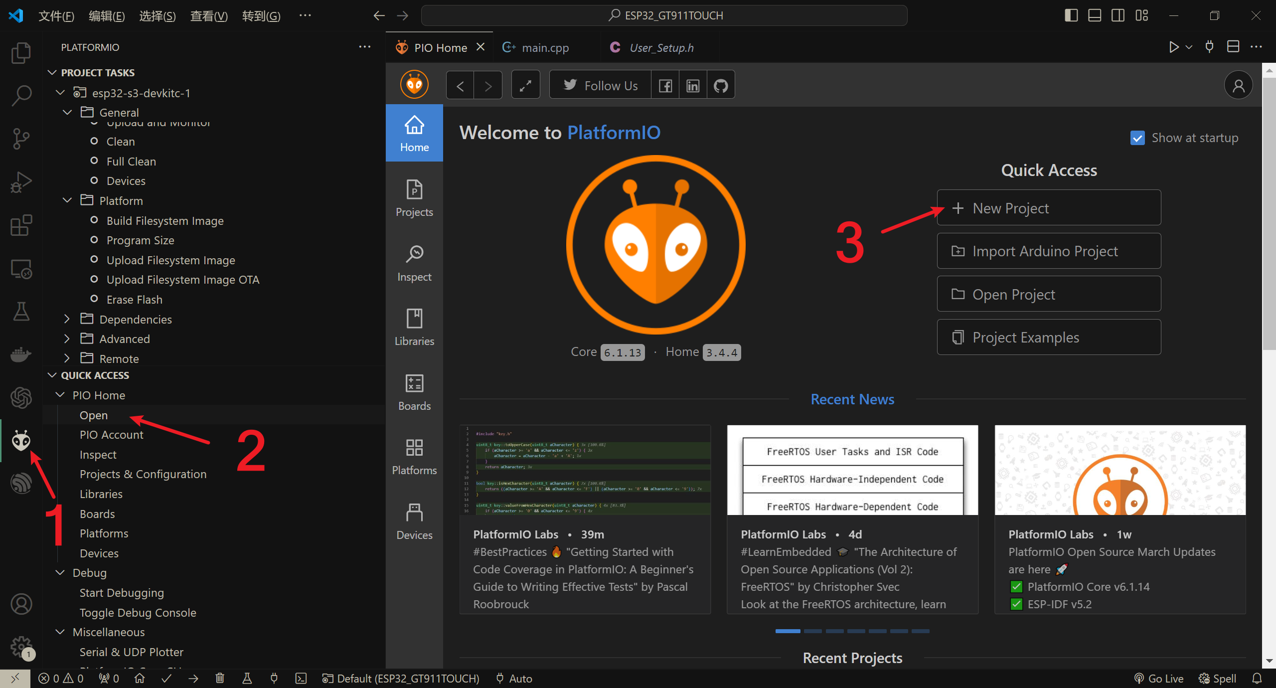
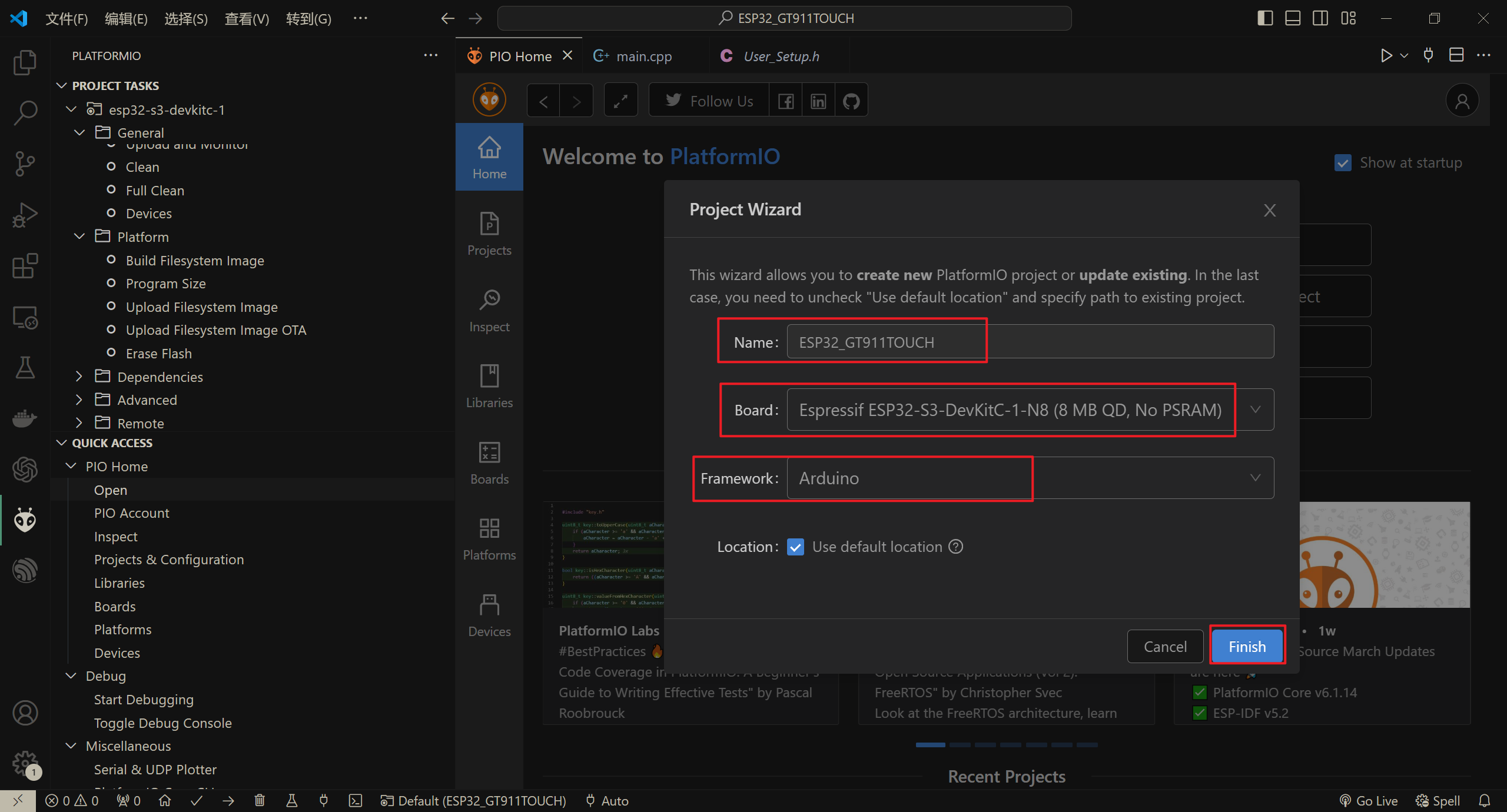
依次设置工程名,开发板,框架
屏幕测试
添加TFT_eSPI
添加屏幕驱动库
TFT_eSPI,按如下图顺序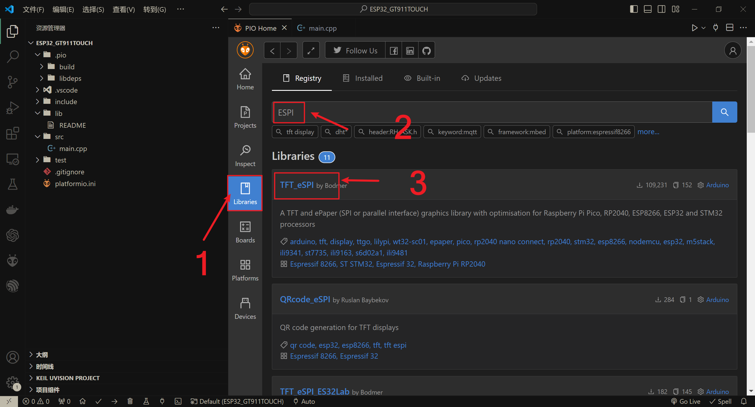
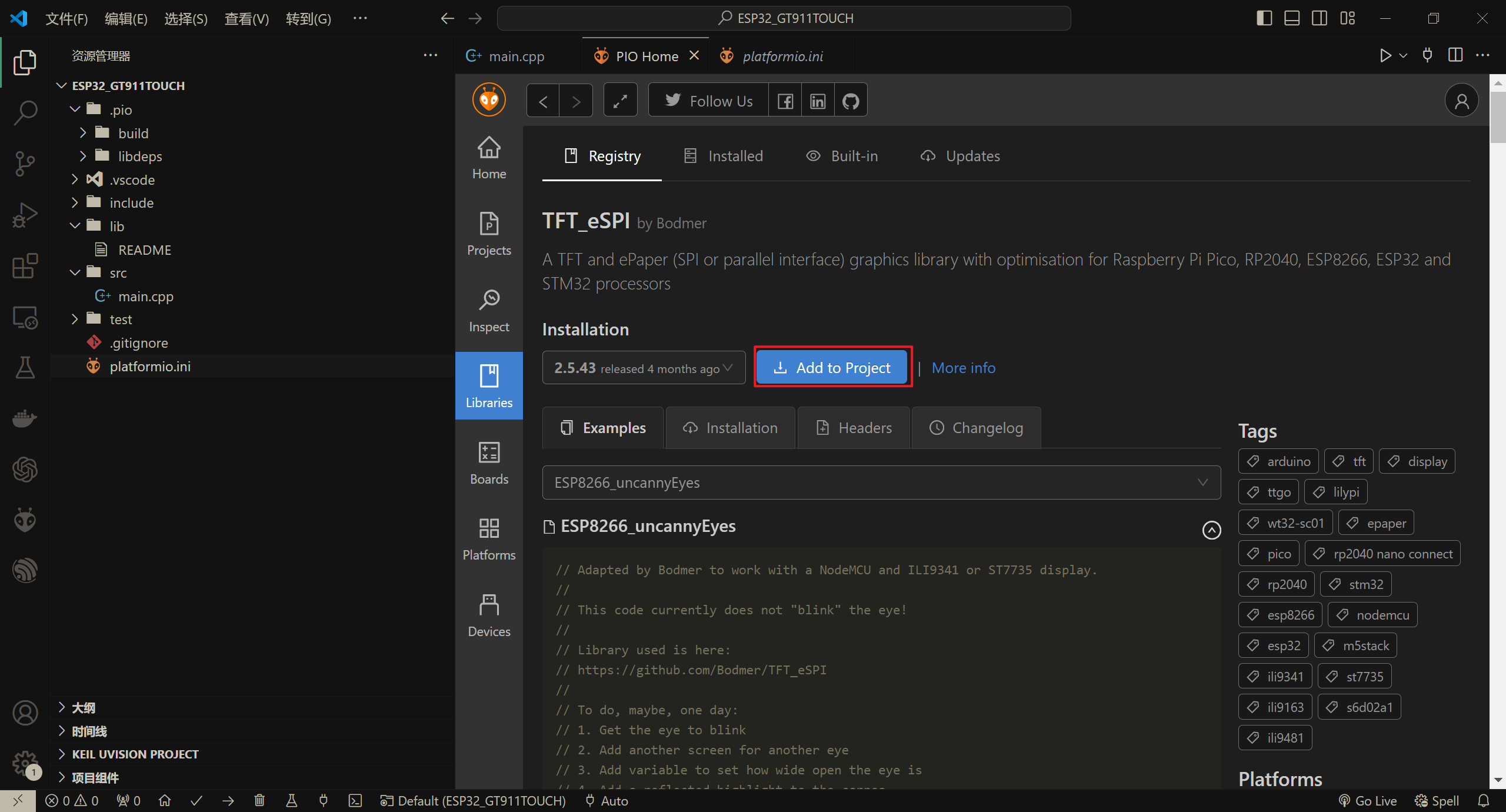
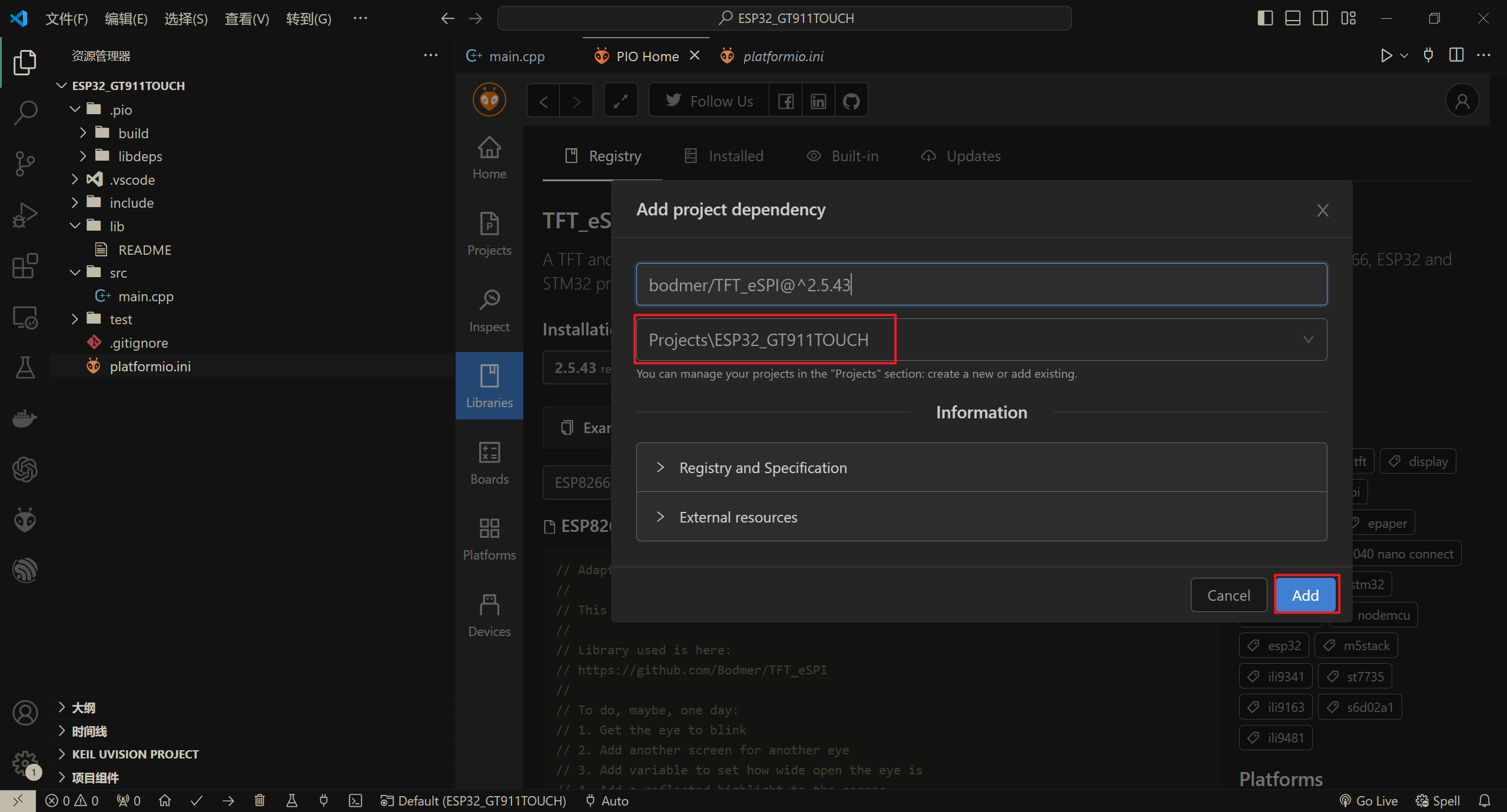
添加TFT_eSPI到工程
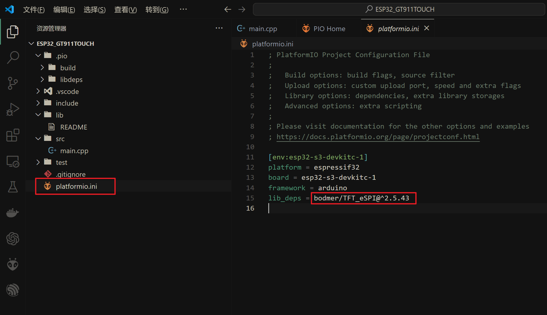
打开配置文件,可以看到已成功添加库
修改TFT_eSPI
打开
.pio\libdeps\esp32-s3-devkitc-1\TFT_eSPI\User_Setup.h文件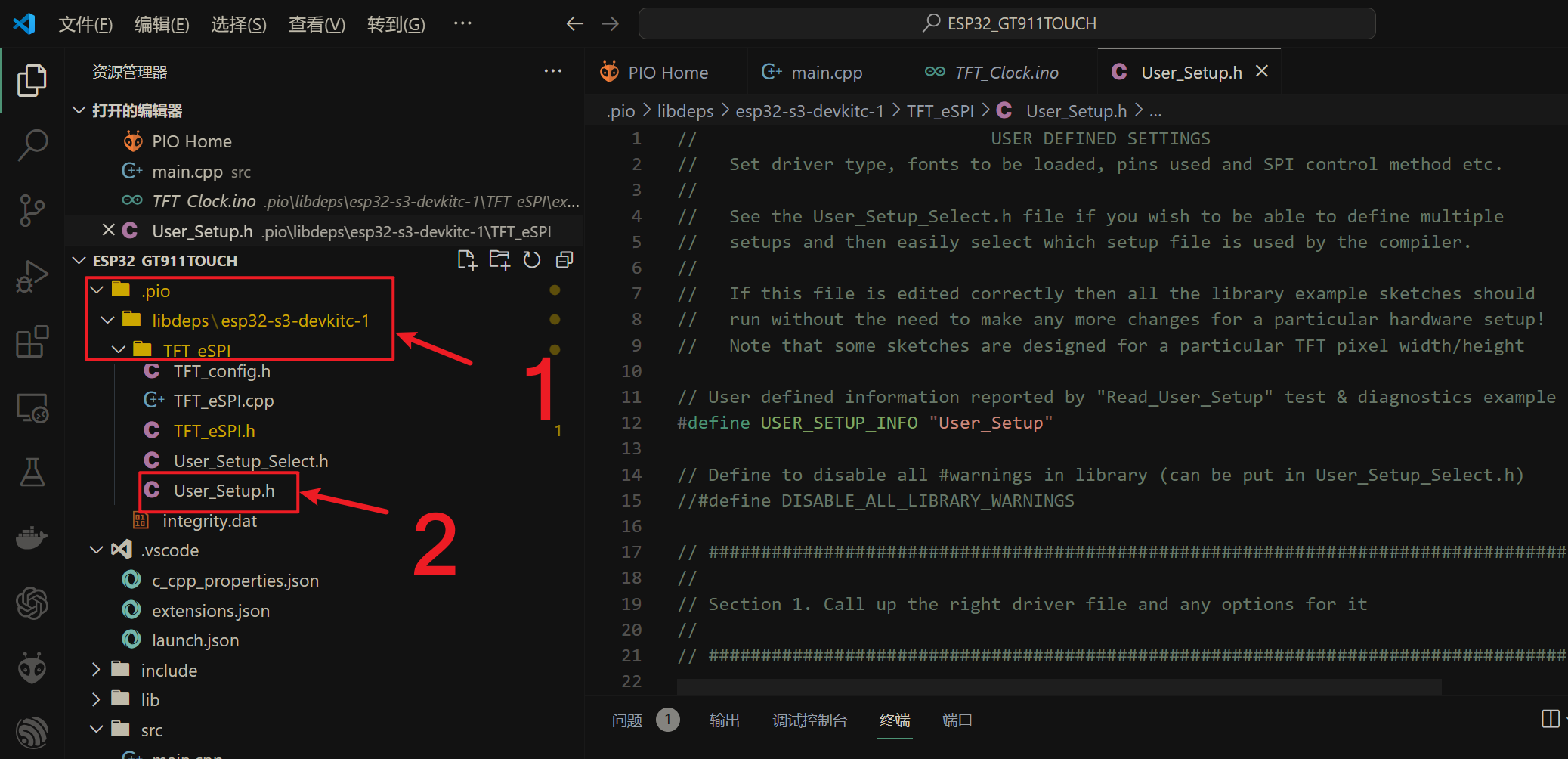
根据屏幕驱动芯片解注释
1 | // Only define one driver, the other ones must be commented out |
- 根据屏幕大小设置宽高
1 | // For ST7789, ST7735, ILI9163 and GC9A01 ONLY, define the pixel width and height in portrait orientation |
- 根据连线设置引脚
1 | // ### EDIT THE PIN NUMBERS IN THE LINES FOLLOWING TO SUIT YOUR ESP32 SETUP ### |
修改main.cpp
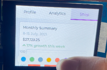
在屏幕上从上到下分别显示红绿蓝三色,以及白色文字,用来测试屏幕颜色显示是否正常。
1 |
|
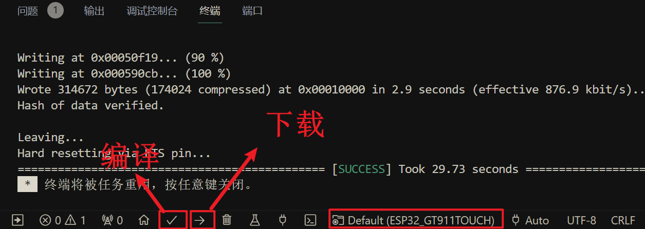
下载调试
编译下载
根据屏幕显示情况修改
User_Setup.h文件
如果颜色反转(白色显示为黑色),如下图所示,则取消下一个注释,尝试两个选项,其中一个选项应该纠正反转。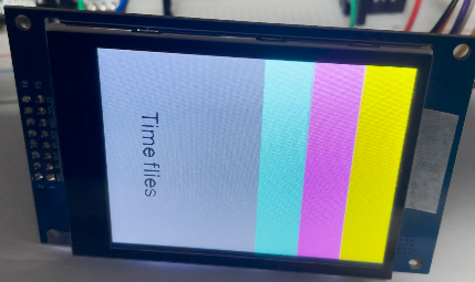
1 | // If colours are inverted (white shows as black) then uncomment one of the next |
修改后,如下图所示,白色正常显示,但是RGB顺序存在问题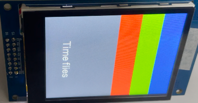
仅对于ST7735, ST7789和ILI9341,如果显示器上的蓝色和红色交换,则定义颜色顺序,一次尝试一个选项来找到显示的正确颜色顺序
1 | // For ST7735, ST7789 and ILI9341 ONLY, define the colour order IF the blue and red are swapped on your display |
修改后,如下图所示,RGB顺序正常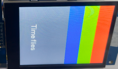
LVGL测试
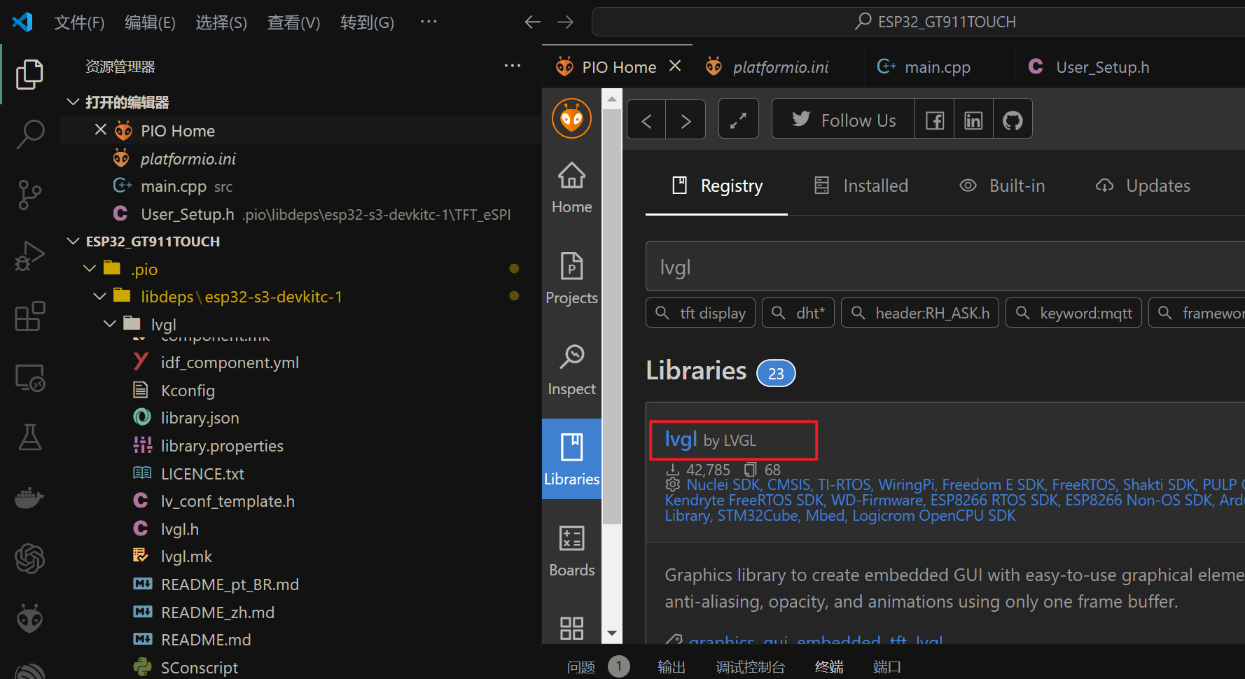
添加LVGL
根据实际情况,选择lvgl版本

触摸测试
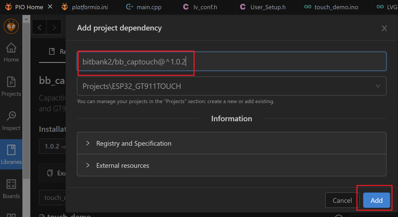
添加bb_captouch
修改main.cpp
添加头文件
1
设置触摸芯片引脚
1
2
3
4
5// These defines are for a low cost ESP32 LCD board with the GT911 touch controller
设置参数
1
2BBCapTouch bbct;
const char *szNames[] = {"Unknown", "FT6x36", "GT911", "CST820"};初始化
1
bbct.init(TOUCH_SDA, TOUCH_SCL, TOUCH_RST, TOUCH_INT);
修改
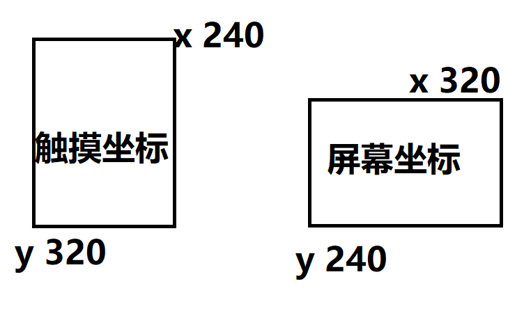
my_touchpad_read函数这里的x,y坐标需要根据实际情况修改
1
2
3
4
5
6
7
8
9
10
11
12
13
14
15
16
17
18
19
20/*Read the touchpad*/
void my_touchpad_read( lv_indev_drv_t * indev_driver, lv_indev_data_t * data )
{
TOUCHINFO ti;
if(bbct.getSamples(&ti))
{
data->state = LV_INDEV_STATE_PR;
/*Set the coordinates*/
data->point.x = screenWidth - ti.y[0];
data->point.y = ti.x[0];
Serial.print( "Data x " );
Serial.println( screenWidth - ti.y[0] );
Serial.print( "Data y " );
Serial.println( ti.x[0] );
}
else
{
data->state = LV_INDEV_STATE_REL;
}
}
修改完成
最终main.cpp文件内容如下
1 |
|
编译下载
触摸显示效果如下图所示